
Beamline Phone Number:
+44 (0) 1235 778418
Principal Beamline Scientist:
Dave Allan
Tel: +44 (0) 1235 778644
E-mail: [email protected]
Email: [email protected]
Tel: +44 (0)1235 4494052
Once the robot has loaded a sample, an initial centring attempt starts automatically. This uses image recognition on OAV2 to put the left-most thing it can see on a set cross-hair. This is then followed by a similar routine using the on-axis camera (OAV1).
There are 2 main causes of failure:
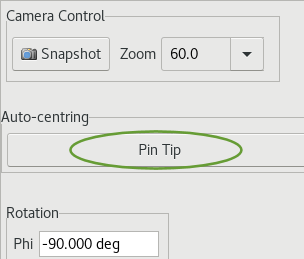
1) The sample-Z stage is in an error state - pressing the + or – button in the DIFF1S window from the synoptic normally works to clear it. See section 1b of the Robot Help page.
Click on the Pin Tip Centring button to run the auto centring script once the error is cleared.
2) The sample is contaminated with fluff or the loop is missing and the routine tries to put this on the cross-hair, but it needs to move the sample stages beyond the limit.
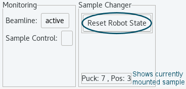
You will need to click on the Reset Robot State button to change the robot status and allow the GDA to control the sample stages for centring – this can be found on the far right of the top banner of the GDA (same section as the baton).
Please Note: The centring should always need to be checked manually as the auto centring is not guaranteed to do an accurate job.
Centre the crystal in GDA in the![]() tab by left clicking on the crystal to bring it to the cross-hair
tab by left clicking on the crystal to bring it to the cross-hair
The camera view can be optimised to fit the window space by clicking on![]()
If auto centring has failed, it helps to start at zoom level 30 then make final adjustments at zoom level 90. Click on the down arrow to select the required zoom level from the dropdown list ![]()
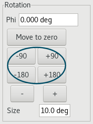
Use the +/-90 and +/-180 buttons to check the centring at 90 degree offsets e.g., 0°, 90°, 180° and 270°, but the centring will work from any starting angle. Keep an eye on the phi angle – the limits are set to +/- 1000 but phi will unwind before the data collection starts.
If you cannot see the crystal to start with, at zoom 30, OAV2 to guide you and either click in the OAV window or use the nudge buttons (the directions of movement are the same for both cameras).
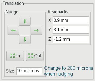
Rotate phi 90 degrees to see if the sample comes into view. If it doesn’t, again nudge the sample towards the crosshair on OAV2.
NOTE: The cross-hair positions on OAV2 and in the GDA are a guide to the position of the centre of rotation of the goniometer and are usually very close, but it is possible that the true centre is slightly off the cross-hair. Try to align the crystal so that its centre of mass does not move as the crystal is rotated.
Once the crystal is fully in view, it can be measured by left-clicking the mouse and dragging a line along the length of the crystal – be careful not to just click and move the sample!
For more accurate measurements, change the phi angle so the crystal is aligned with the camera first.
If the red text showing the size is too small and blurred, try scrolling on the image to zoom in - this should make the text more legible.
TIP: As it is very easy to just click rather than click and drag the mouse, it may be better to measure the crystal before fine tuning the crystal centring.
Auto Mode
A series of 4 snapshots are automatically taken at 90° intervals (0°, 90°, 180°, 270°) at the start of a data collection, as long as the collection is started from a position where the backlight is in. These images are visible in ISPyB.
Usually, the snapshots will be associated with the first screening run, but not retaken for subsequent data collections on the same crystal.
The system can be forced to take another set of snapshots by first clicking on the "Prepare Sample Mount" button in the list of scripts within the Axis Control tab, (to move the goniometer to a position where the backlight comes back in) and then setting the data collection running - this could just be a single image if snapshots are required at the end of an experiment.
Manual Mode
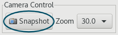
It is also possible to take snapshots manually by clicking on the Snapshot button within Camera Control.
Images can only be saved within the jpegs folder of your visit directory (this is where the snapshots taken automatically are also saved).
Unfortunately, any measurements added are not saved.

Diamond Light Source is the UK's national synchrotron science facility, located at the Harwell Science and Innovation Campus in Oxfordshire.
Copyright © 2022 Diamond Light Source
Diamond Light Source Ltd
Diamond House
Harwell Science & Innovation Campus
Didcot
Oxfordshire
OX11 0DE
Diamond Light Source® and the Diamond logo are registered trademarks of Diamond Light Source Ltd
Registered in England and Wales at Diamond House, Harwell Science and Innovation Campus, Didcot, Oxfordshire, OX11 0DE, United Kingdom. Company number: 4375679. VAT number: 287 461 957. Economic Operators Registration and Identification (EORI) number: GB287461957003.

 Crystallography